Push-Pull Vs. Open Drain
Digital solid-state magnetic sensors, such as Coto Technology’s RedRock® TMR sensors, have two output options – Push-Pull and Open Drain. A firm understanding of each option helps engineers to produce efficient, cost effective, forward-thinking designs for their devices.

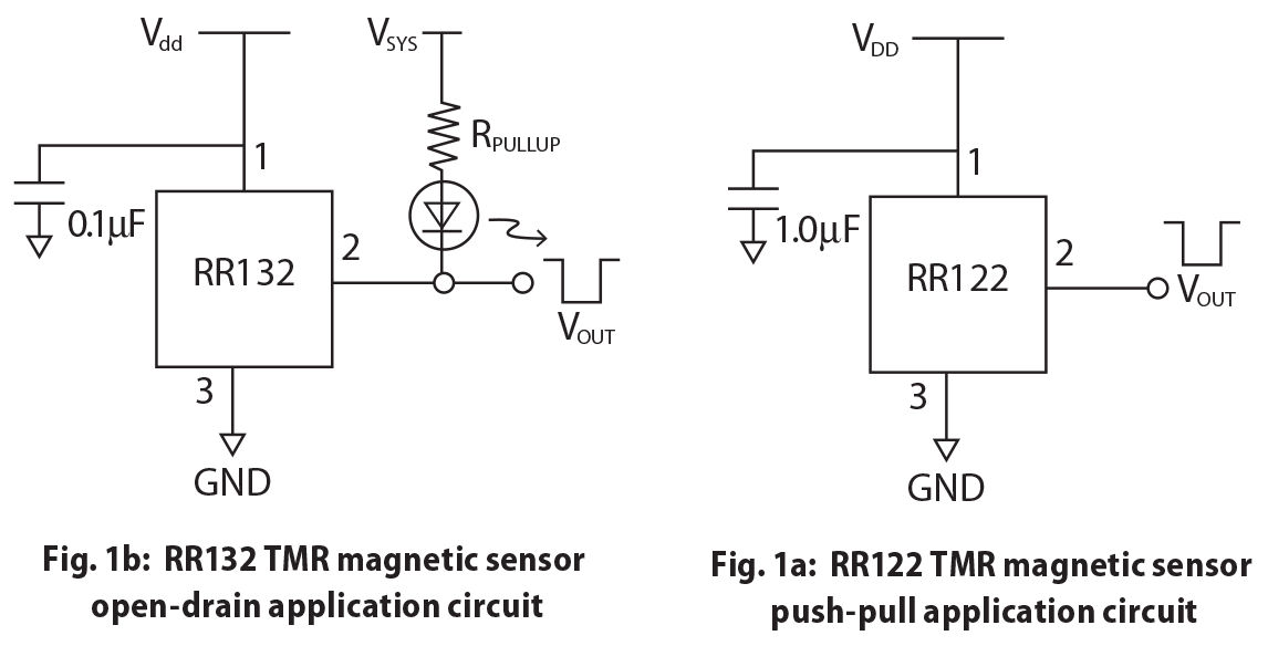
A push-pull output (Figure 1a), also called a “totem pole” output, provides an unambiguous voltage output signal which is normally driven to a high-logic level when only a low magnetic field is present, but which is driven low in a magnetic field that is higher than the operating threshold (Bop) for the part. This type of response is called “active low,” because the output voltage is driven low when the sensor is activated. By “high” we mean an output voltage that is at least 90% of the supply voltage (Vdd),and by “low” we mean < 10% of the supply voltage. When the field magnitude drops to the release threshold (Brp), the output is driven high again. The difference between the magnetic field magnitudes that turn the part on and off is termed the “hysteresis,” and it’s an inherent feature that prevents a switch from “chattering” when the magnetic field is close to the threshold between on and off.
Digital solid-state magnetic sensors, such as Coto Technology's RedRock® TMR sensors, have two output options - Push-Pull and Open Drains. A firm understanding of each option helps engineers to produce efficient, cost effective, forward-thinking designs for their devices.
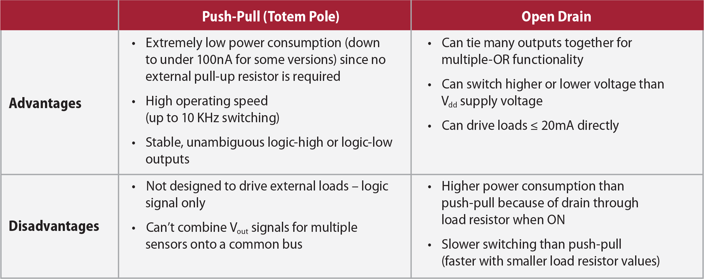
Depending on the specific part type, the sensor may have been designed to be unipolar (turns on and off according to a specific field polarity), omnipolar (operates in either a North pole or South pole field), or bipolar (latches on in a North field and releases in a South field). Advantages of push-pull are very low power consumption, (< 100 nA for some part types) very high operating speed, and unambiguous, noise-free outputs.

For certain applications, however, an open drain configuration (Figure 1b) may be more useful. In this configuration a single internal MOSFET is normally non-conducting in the absence of a magnetic field that is greater than Bop. While a push-pull sensor has two MOSFETs that alternately conduct to provide high or low output signals, an open drain sensor has only one MOSFET. When a magnetic field turns the open-drain sensor on, the MOSFET conducts, allowing current to sink through the pull-up resistor to ground. A load in the same line (an LED is shown in Fig. 1b) can be powered directly, provided the current does not exceed20 mA. The voltage at Vout can also be sent to an external logic circuit.
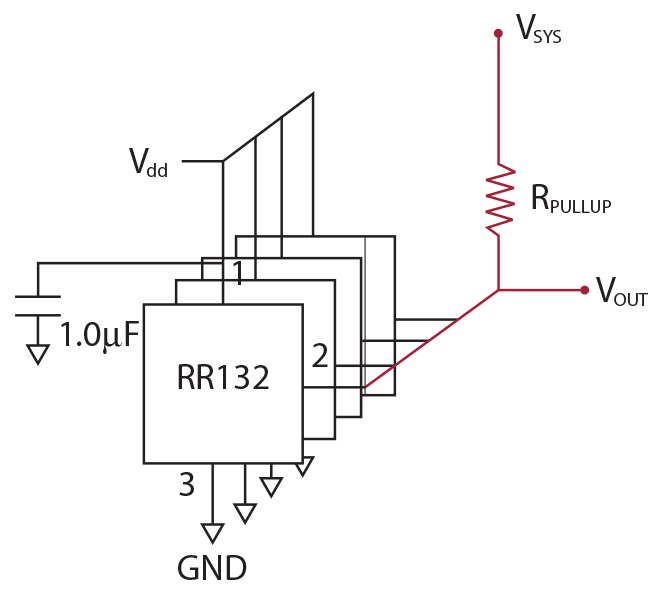
The advantages of the open-drain configuration are three-fold: first, the ability to directly drive a load; second, (and probably more importantly) the ability to switch external sources that may have higher or lower voltages than Vdd; and third, multiple open-drain sensors (such as the RR132) can be connected in a multiple-OR configuration. Figure 2 shows an example with four sensors. If a magnetic field turns one or more of the sensors ON, the common bus line shown in red is pulled low. This circuit has many applications such as resistor ladders for level sensing and loop circuits for security applications, where a response is required if any one of many sensors is triggered.


For further background reading on push-pull and open-drain, digital devices, consult The Art of Electronics by Horowitz and Hill, Cambridge University Press, ISBN 0-521-37095-7.
To find out more about the sensors described here, or to requestpart samples, please visit:
www.cotorelay.com or contact appsupport@cotorelay.com.


