
Using RedRock® TMR Magnetic Sensors For Speed And Direction Estimation In Rotating Systems

Background
Utility meters (gas, water), motor commutation and distance measurement are among an ever expanding range of applications which require a measurement of rotation speed and/or direction of rotation. Traditional methods, such as optical methods, are rapidly being replaced with magnetic sensing methods due to the latter’s inherent simplicity, ability to operate through barriers, and cost advantages due to better integration. Magnetic field sensors using Tunneling Magnetoresistance (TMR)bring additional advantages, such as the ability to operate at a substantially lower operating current while providing greater sensitivity. These enhancements extend the operational life of a battery-operated device, and can reduce the size of the device– both of which directly improve user experience.
The RedRock series of sensors from Coto Technology utilize TMR technology and ultra low power CMOS to produce ultralow power sensors, with high sensitivity. The RR122 bipolar sensors operate with as little as +/-10 Gauss magnetic field (1Millitesla) for turn-on and turn-off, and, with a latched output, are ideally suited for use in rotating systems for speed and direction measurement. Such a small magnetic field is easily created with a small and inexpensive magnet. These sensors operate with 1.7-5.5V and are available in SOT-23-3 and LGA packages, and in a combination of sampling frequency and sensitivity options. In the case of battery-powered applications where power conservation is essential, some RR122 bipolar TMR sensors offer an optional “Turbo Mode.” This feature permits purposeful toggling between low and high frequency viaan enable pin, with the low frequency mode consuming less power than the high frequency mode.
Sensor Characteristics and Speed Measurement
RedRock RR122 bipolar sensors are sensitive to the magnetic field component in the plane of the sensor and parallel to the long axis of the package (pin-1 to pin-2), as shown in Figure-1 a.Figure-1b shows various magnet positions around the sensor in 3-dimensions that produce a strong field at the sensor in the direction of sensitivity.

The output of a latching bipolar sensor (such as the RR122-3C63-511 and similar) is switched to the ON (low) state when the field at the sensor falls to less than the Bop – the operate point (-10 Gauss) – and is latched. Similarly, the output switched to the OFF (high) state when the field at the sensor rises to greater than Brp – the release point (+10 Gauss) – and remains latched. Figure-2a shows the sensor output as a function of magnetic field strength at the sensor. When the magnetic field variation is shown as a function of time, output from the sensor is a digital signal as shown in Figure-2b. This is useful in a rotating application where speed and direction need to be measured.


In a simple implementation, a circular magnet with North and South poles on the diameter is mounted on the rotating shaft, as shown in Figure-3a. The north and south magnetic fields from the magnet alternately sweep over the sensor, once every rotation. The output of the RR122 switches to digital high when the north pole sweeps over the sensor with B>Brp, and switches to digital low when the south pole sweeps over the sensor with B<Bop, as shown in Figure-3b. As a result, the output from the RR122 will cycle from low to high and then back to low for every rotation. Therefore, rotation rate (rev/sec) can be determined by simply measuring the frequency of the sensor output.


Step and Direction Sensing
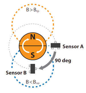
In applications where the direction of rotation needs to be measured in addition to the speed of rotation, two sensors– Sensor A and Sensor B – are used. They are positioned at a radial distance which ensures field strength at the sensor will be greater than Brp and less than Bop as the north and south poles sweep by and at 90 degrees from each other, as shown in Figure-4a. In this arrangement, frequency of Sensor A or Sensor B can be used to estimate rotation rate.
Rotation frequency = Output frequency of Sensor-A (or Sensor-B)
Rotation RPM = Rotation frequency/60
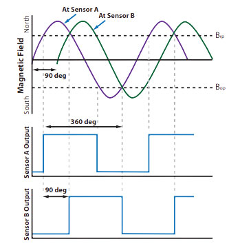
Phase difference in the outputs of Sensors A and B – as shown in Figure-4b – is used to determine direction of rotation. In Order to determine the phase relation, the combination of outputs from both sensors is considered as a digital state, and a change in the state is registered as a step, which, because of the arrangement of the sensors, corresponds to a 90 degree rotation of the shaft.
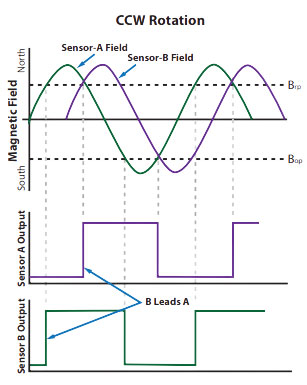
When the magnet rotates in the CW direction, it sweeps past Sensor A, then past Sensor B, and when it rotates CCW, its weeps past Sensor B first, and then past Sensor A. Figure-5aand Figure-5b show output signals from Sensors A and B for CW and CCW rotation, respectively. The direction of rotation therefore determines which of the two sensor outputs leads the other. During CW rotation, Sensor A is triggered first, then Sensor B – i.e., A leads B. During CCW rotation, B leads A.

As the magnet turns through a full rotation, outputs of Sensors A and B combine to produce digital states which are shown in Figure-6a for CW rotation, and in Figure-6b for CCW rotation.
From Figures 6a and 6b, it is evident that output states from Sensors A and B for CCW rotations follow in reverse order compared to CW rotation. Therefore, direction of rotation can be determined by comparing the current state of Sensors A and B, to the previous state. For example, in Figure 6a, considerate current state to be step-2, (A=High, B=High); if the previous state was A=High, B=Low, (Step-1 in CW) then the rotation is CW. However if the previous state was A=Low, B=High (Step-3in CW, = step-1 in CCW), then the rotation is CCW.
In a simple implementation, rotation speed and direction can be decoded from the output signals of Sensor A and B, with the use of a D-flip-flop, as shown in Figure-7.

The lookup algorithm for determining rotation direction can also be implemented in software running on an embedded microcontroller. A flow chart for the software implementation is shown in Figure-8, where change in outputs of Sensor A and B are detected using interrupts or polling.
For high-speed applications, this software implementation may prove too slow. In such cases, a digital state machine – such as a Field Programmable Gate Array (FPGA), or a Programmable Logic Device (PLD) may be used to decode the sensor signals and derive speed and direction signals.
In industrial systems where electrical noise may be superimposed on the sensor signals, and also in more robust systems, where a high degree of reliability is required, a separate high frequency oversampling clock may be used to monitor the outputs of Sensors A and B at a much faster rate, and register a valid output condition only after multiple clock cycles confirm the same states of Sensors A and B. A valid change in the outputs of A or B then corresponds to a step, which is further decoded with the algorithm similar to that shown in Figure-8.

Concluding Remarks
A digital latching bipolar sensor, such as RR122 from Coto Technology, can easily be used for speed and direction measurement in rotating systems, with the use of a simple D-flip flop orby using an algorithm implemented in software running on an embedded microcontroller. The sensor’s high sensitivity(+/-10G) allows the use of smaller and/or less expensive magnets. Further, because of the sensor’s very low current consumption, operational life of a battery operated device can be greatly extended.
For further application assistance, please contact Coto Technology’s Sales and Applications Engineering team. (appsupport@cotorelay.com).